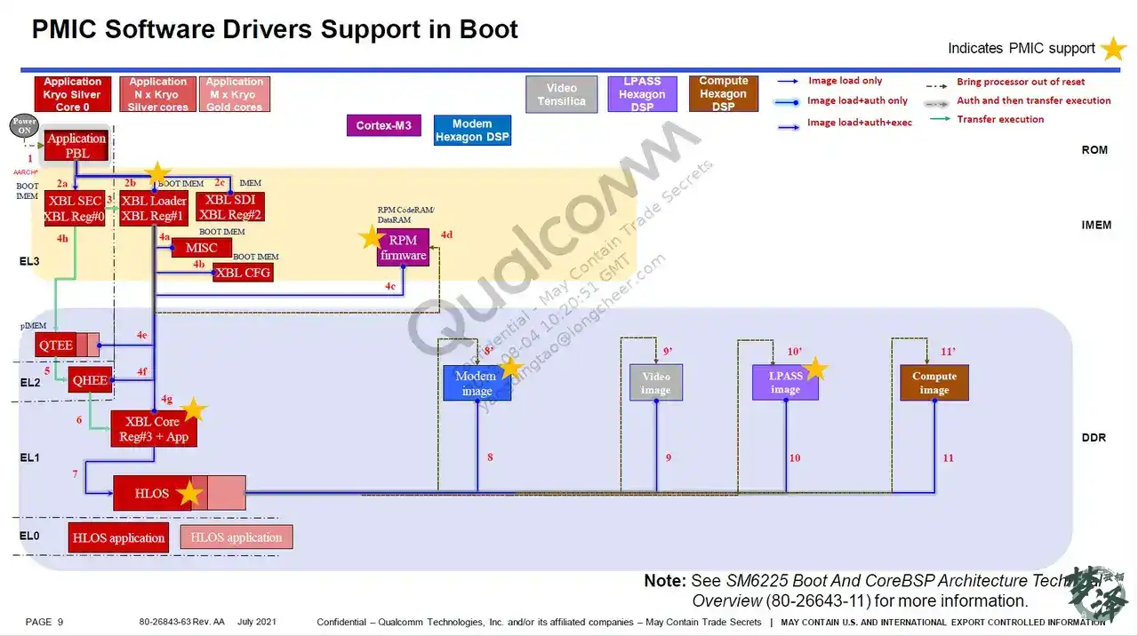
Why this boot path matters
When working on UEFI-stage bring-up, platform porting, or hard-to-locate boot failures, it helps to have a clear picture of how the Qualcomm Android boot chain actually progresses. The path from the earliest immutable ROM code to ABL is not just a sequence of handoffs; each stage establishes hardware state, memory, security context, and execution environment for the next one.
This walkthrough focuses on the path from Qualcomm’s first-stage boot code into XBL and then into the UEFI/ABL world.
Cold boot on a Qualcomm platform
After power-on, execution begins with APPS PBL, then proceeds through XBL SEC and XBL Loader, which in turn bring up XBL CORE / APPSBL, and finally transfer control toward HLOS.
Before looking at the code, it helps to review two ARM concepts that appear repeatedly in Qualcomm boot code: exception levels and secure state.
Exception levels
<table> <thead> <tr> <th>Exception level</th> <th>Typical software running there</th> </tr> </thead> <tbody> <tr> <td>EL0</td> <td>Application</td> </tr> <tr> <td>EL1</td> <td>Linux kernel / OS</td> </tr> <tr> <td>EL2</td> <td>Hypervisor</td> </tr> <tr> <td>EL3</td> <td>Secure Monitor (ARM Trusted Firmware)</td> </tr> </tbody> </table>A few practical points:
- For ELx where x < 4, a larger x means a higher privilege level.
- EL0 is unprivileged execution.
- EL2 has only the Non-secure state.
- EL3 has only the Secure state and supports switching between Secure and Non-secure execution for EL0/EL1.
- EL0 and EL1 must exist; EL2 and EL3 are optional in the architecture.
- On exception entry, the exception level can only stay the same or move higher.
- On exception return, the level can only stay the same or move lower.
- The level selected on exception entry is the target exception level.
- Each exception level has a default target level, and registers can also influence that target, but it cannot be EL0.
- A PE running at a given exception level can access both: resources for its current EL/security-state combination, and resources available to lower exception levels, subject to security-state rules.
Secure and non-secure state
<table> <thead> <tr> <th>State</th> <th>Characteristics</th> </tr> </thead> <tbody> <tr> <td>Non-secure</td> <td>EL0/EL1/EL2, can access only the Non-secure physical address space</td> </tr> <tr> <td>Secure</td> <td>EL0/EL1/EL3, can access both Secure and Non-secure physical address space and provides hardware-backed isolation</td> </tr> </tbody> </table>What each early boot stage is responsible for
APPS PBL
When PBL starts, only CPU Core 0 is enabled. The firmware lives in on-chip ROM and is fixed by Qualcomm; external developers cannot modify it.
Its main responsibilities are:
- Initialize the secure execution environment so later XBL APPS code can run correctly.
- Choose the boot device based on boot GPIO configuration, such as NAND or USB.
- Check GPIO state to decide whether to enter Emergency Download mode, where a full system image can be downloaded with tools such as QFIL.
- Use L2 TCM to load XBL1 ELF, OCIMEM, and RPM CodeRAM code.
XBL
Starting with XBL, execution is now using the system image that was built and flashed into eMMC or UFS. XBL mainly prepares hardware and security state.
Its responsibilities include:
- Initializing buses, DDR, clocks, CDT, and starting QSEE, QHEE, RPM firmware, and XBL core images.
- Enabling memory dump through USB and Sahara, watchdog support, and RAM dump to SD support.
- Initializing the USB driver, USB charging support, thermal checks, PMIC drivers, and DDR training.
XBL Core: UEFI or LK / ABL
XBL core corresponds to what used to be thought of as the bootloader layer. Its job is to initialize display support, provide fastboot, and boot the HLOS kernel.
One detail that is easy to miss: even in ABL, only CPU Core 0 is active. The remaining CPU cores are brought up only after entering the HLOS kernel.
Code layout and build location
Older LK-related code has moved under boot_images/QcomPkg, and the build flow is different from earlier layouts.
#编译指令
cd boot_images/QcomPkg/SocPkg/DivarPkg
python …/…/buildex.py --variant LAA -r RELEASE -t DivarPkg,QcomToolsPkg

#clean指令
python …/…/buildex.py --variant LAA -r RELEASE -t DivarPkg,QcomToolsPkg --build_flags=cleanall
The code base is under:
${BP_ROOT}/BOOT.XF.1.4/boot_images/

From PBL into SBL
PBL is the very first code executed after power-on. It resides in ROM, is not open source, and cannot be inspected directly. PBL then starts SBL.
SBL1 initializes enough hardware to continue the boot process: it brings up DDR, loads TrustZone, loads RPM firmware, and loads ABL.
From SBL onward, execution has entered the XBL path. The SBL1 usually referenced in practice corresponds to XBL REG#1, with assembly entry in:
BOOT.XF.4.1/boot_images/QcomPkg/SocPkg/Library/XBLLoaderLib/sbl1_Aarch64.s
sbl1_entry_init_stack:
  // -------------------------------
  // add more assembly init code here for entering sbl1_main_ctl//
  // restore PBL parameter and enter sbl1_main_ctl
  // -------------------------------
MOVw0,w7BLsbl1_main_ctl    //跳转到C环境继续
sbl1_main_ctl: where the C-side boot flow really begins
The main role of sbl1_main_ctl is to perform the early initialization required for later stages to run, especially critical peripherals and RAM.
voidsbl1_main_ctl(boot_pbl_shared_data_type *pbl_shared){
  DALResultbsy_wait_init;

  /* Configure Domain access control register */
mmu_set_dacr(DACR_ALL_DOMAIN_CLIENTS); //配置域访问控制器

  /* Retrieve info passed from PBL*/
sbl1_retrieve_shared_info_from_pbl(pbl_shared); //将pbl传过来的信息保存到pbl_shared

  /* Initialize shared functions structure - provides other images with function pointers in Loader */
boot_shared_functions_register(); //初始化共享函数结构

  /* Initialize SBL memory map */
sbl1_populate_initial_mem_map(&bl_shared_data); //初始化SBL内存映射

  /* Calculate the SBL start time for use during boot logger initialization. */
sbl_start_time =CALCULATE_TIMESTAMP(HWIO_IN(TIMETICK_QTIMER_CLK));
sbl_start_time_mpm =CALCULATE_MPM_TIMESTAMP(HWIO_IN(TIMETICK_CLK));

  /* Initialize busywait module Note: required before logger init due to uart driver dependency on busywait */
BL_VERIFY((bsy_wait_init=boot_busywait_init()) ==DAL_SUCCESS, (uint16)bsy_wait_init|BL_ERROR_GROUP_BUSYWAIT);

  /* Enable qdss workaround*/
BL_VERIFY(boot_clock_debug_init() ==TRUE,FALSE|BL_ERROR_GROUP_CLK );

  /* Enter debug mode if debug cookie is set */
sbl1_debug_mode_enter(); //sbl1 debug mode,其实就是一个while,知道jtag获取到地址。判断cookie是否匹配,以确定是否进入jtag调试模式

  /* Initialize the stack protection canary */
boot_init_stack_chk_canary();//堆栈保护,随机初始化多出数值,避免堆栈溢出攻击

  /* Initialize boot shared imem */
boot_shared_imem_init(&bl_shared_data);
  //进行SBL间数据共享初始化,数据类型bl_shared_data_type,先进行溢出判断,检查魔数是否匹配,否则写0xFF,并更新版本和魔数值

  /* Initialize the ChipInfo driver */
ChipInfo_Init();

  /* Initialize the QSEE interface */
sbl1_init_sbl_qsee_interface(&bl_shared_data, &sbl_verified_info);
  //初始化QSEE(Secure Excution Environment)安全执行环境接口,清零interface,初始化完成后并为QSEE接口分配魔数和version号以及复位请求,调用boot_ddr_enter_self_refresh进行DDR自我更新和调用boot_ddr_exit_self_refresh退出自我更新。并使用PBL提供的验证信息更新QSEE的接口。更新bl_shared_data中的qsee中的boot_image_entry入口点。QSEE一般是为APP提供安全运行环境,它将整体系统分为安全运行环境和常规运行环境,像指纹识别、人脸识别均需要运行在安全环境下,而像普通APP则运行在常规环境下,QSEE一般和Trust Zone共同完成安全运行环境和常规运行环境的搭建
  /* Initialize dal heap using internal memory */
boot_DALSYS_HeapInit(boot_internal_heap,BOOT_INTERNAL_HEAP_SIZE,FALSE);

  /*Initialize DAL, needs to be called before modules that uses DAL */
boot_DALSYS_InitMod(NULL);

  /* Initialize boot logger and start the log timer.
     This must be done after sbl1_retrieve_shared_info_from_pbl
     and boot_secboot_ftbl_init. */
sbl1_boot_logger_init(&boot_log_data,pbl_shared);
  //配置GPIO使能串口,调用sbl1_boot_logger_init进行串口及定时器和相关log初始化,便于boot_log_message打印log信息。串口硬件初始化:sbl1_boot_logger_init-> boot_log_init-> boot_log_init_uart-> boot_uart_init> uart_initialize-> uart_open(&uart_debug_handle, UART_DEBUG_PORT, &c),最后一个函数位于QomPkg/Library/UartQupv3Lib/UartXBL.c, 函数内调用UART_LOG_0(INFO,"+uart_open")打印串口开启log,有待探究,uart_open调用register_init函数配置寄存器,函数内调用REG_OUT;配置相关寄存器。

boot_log_set_meta_info(boot_log_data.meta_info_start);

  /* Set hash algorithm */
BL_VERIFY(boot_set_hash_algo(SBL_HASH_SHA256) ==BL_ERR_NONE,BL_ERR_UNSUPPORTED_HASH_ALGO|BL_ERROR_GROUP_BOOT);

  /* Call sbl1_hw_init to config pmic device so we can use PS_HOLD to reset */
sbl1_hw_init();
  //硬件初始化,调用boot_Tsens_Init初始化温度传感器;调用boot_qusb_ldr_utils_hs_phy_nondrive_mode_set将高速QUSB2置位为非驱动模式;IIC时钟初始化,因为EEPROM使用IIC协议,初始化IIC时钟来确保后面的EEPROM能够得到正常的初始化。首先根据宏定义FEATURE_BOOT_FAST_DEBUG判断是否进入debug mode->boot_debug_mode_enter();

#if defined (FEATURE_DEVICEPROGRAMMER_IMAGE) || defined (FEATURE_DDI_IMAGE)
  /* Enter device programmer does not return */
device_programmer_init(&bl_shared_data,pbl_shared);
#else/* Store the sbl1 hash to shared imem */
boot_store_tpm_hash_block(&bl_shared_data, &sbl_verified_info);

  /*-----------------------------------------------------------------------
    Process the target-dependent SBL1 procedures
  -----------------------------------------------------------------------*/
boot_config_process_bl(&bl_shared_data,SBL1_IMG,sbl1_config_table);
#endif

} /* sbl1_main_ctl() */
Several things in this function matter in practice:
- It sets up memory access policy and internal shared data structures.
- It records timing for boot logging.
- It enables UART-backed logging very early.
- It initializes stack canary protection.
- It initializes the QSEE interface and shared boot IMEM.
- It performs platform hardware initialization before image loading proceeds.
- It eventually calls
boot_config_process_bl, which is the core image-processing path for SBL1.
UART logging in SBL
Inside sbl1_main_ctl, logger initialization goes through sbl1_boot_logger_init, which eventually calls boot_log_init_uart to bring up the serial interface.
At this stage, useful logging methods include:
boot_log_dump(boot_log_ram_to_uart)to dump logs stored in RAM to UART.boot_log_message, which is more convenient during bring-up because it writes the log both to RAM and directly to UART.
These function calls line up clearly with what appears in boot-time serial output.
boot_config_process_bl: the central dispatcher in SBL1
This function is the core of the SBL image-processing logic. Its parameters include the shared SBL data structure, the SBL1 image identifier, and the SBL1 configuration table.
It repeatedly calls boot_config_process_entry to process items defined in the configuration table. The table covers subsystems such as PMIC, APDP, QSEE, QHEE, RPM, STI, ABL, and APPSBL.
Each subsystem entry in sbl1_config_table can define:
- pre-load procedures
- load behavior
- authentication behavior
- jump/execute behavior
- post-load procedures
- load-cancel handlers
The code is easier to follow by looking at the generic procedure runner:
boot_config_process_bl->boot_config_process_entry->boot_do_procedures->
#define BOOT_FUNCTION_LEN 48
void boot_do_procedures
(
bl_shared_data_type *bl_shared_data,
boot_function_table_type *procs
)
{
boot_function_table_type *cur_proc;
uint32 func_start_time=0;
char func_name[BOOT_FUNCTION_LEN];
BL_VERIFY( bl_shared_data != NULL, BL_ERR_NULL_PTR_PASSED|BL_ERROR_GROUP_BOOT );
if (procs != NULL)
{
for ( cur_proc = procs; (boot_procedure_func_type)cur_proc->func != NULL; cur_proc++ )
{
func_start_time = boot_log_get_time();
((boot_procedure_func_type)cur_proc->func)( bl_shared_data );
qsnprintf(func_name, BOOT_FUNCTION_LEN ,"%s", cur_proc->func_name);
boot_log_delta_time(func_start_time,func_name);//这边会打印log
}
}
}
//我们需要看这个sbl_config_table,他是在sbl_config.c中配置的
boot_configuration_table_entry sbl1_config_table[] =
{
/* host_img_id host_img_type target_img_id target_img_type target_img_sec_type load auth exec jump exec_func jump_func pre_procs post_procs load_cancel target_img_partition_id target_img_str boot_ssa_enabled enable_xpu xpu_proc_id sbl_qsee_interface_index seg_elf_entry_point whitelist_ptr */
{SBL1_IMG, CONFIG_IMG_QC, GEN_IMG, CONFIG_IMG_ELF, SECBOOT_APDP_SW_TYPE, TRUE, TRUE, FALSE, FALSE, NULL, NULL, apdp_pre_procs, apdp_post_procs, apdp_load_cancel, apdp_partition_id, APDP_BOOT_LOG_STR, FALSE, FALSE, 0x0, 0x0, 0x0, apdp_img_whitelist },
{SBL1_IMG, CONFIG_IMG_QC, GEN_IMG, CONFIG_IMG_ELF, SECBOOT_OEM_MISC_SW_TYPE, TRUE, TRUE, FALSE, FALSE, NULL, NULL, NULL, NULL, oem_misc_load_cancel, multi_image_partition_id, OEM_MISC_BOOT_LOG_STR, FALSE, FALSE, 0x0, 0x0, 0x0, oem_misc_img_whitelist},
{SBL1_IMG, CONFIG_IMG_QC, GEN_IMG, CONFIG_IMG_ELF, SECBOOT_QTI_MISC_SW_TYPE, TRUE, TRUE, FALSE, FALSE, NULL, NULL, NULL, NULL, qti_misc_load_cancel, multi_image_qti_partition_id, QTI_MISC_BOOT_LOG_STR, FALSE, FALSE, 0x0, 0x0, 0x0, qti_misc_img_whitelist},
{SBL1_IMG, CONFIG_IMG_QC, GEN_IMG, CONFIG_IMG_ELF, SECBOOT_RPM_FW_SW_TYPE, TRUE, TRUE, FALSE, FALSE, NULL, NULL, rpm_pre_procs, NULL, rpm_load_cancel, rpm_partition_id, RPM_BOOT_LOG_STR, FALSE, FALSE, 0x0, 0x0, 0x0, rpm_img_whitelist },
{SBL1_IMG, CONFIG_IMG_QC, GEN_IMG, CONFIG_IMG_ELF, SECBOOT_QSEE_DEVCFG_SW_TYPE, TRUE, TRUE, FALSE, FALSE, NULL, NULL, NULL, NULL, qsee_devcfg_load_cancel, qsee_devcfg_image_partition_id, QSEE_DEVCFG_BOOT_LOG_STR, FALSE, FALSE, 0x0, 0x0, 0x0, devcfg_img_whitelist },
{SBL1_IMG, CONFIG_IMG_QC, GEN_IMG, CONFIG_IMG_ELF, SECBOOT_QSEE_SW_TYPE, TRUE, TRUE, FALSE, FALSE, NULL, NULL, NULL, qsee_post_procs, NULL, qsee_partition_id, QSEE_BOOT_LOG_STR, FALSE, FALSE, 0x0, 0x0, 0x0, qsee_img_whitelist },
{SBL1_IMG, CONFIG_IMG_QC, GEN_IMG, CONFIG_IMG_ELF, SECBOOT_SEC_SW_TYPE, TRUE, TRUE, FALSE, FALSE, NULL, NULL, NULL, NULL, sec_load_cancel, secdata_partition_id, SEC_BOOT_LOG_STR, FALSE, FALSE, 0x0, 0x0, 0x0, sec_img_whitelist },
{SBL1_IMG, CONFIG_IMG_QC, GEN_IMG, CONFIG_IMG_ELF, SECBOOT_QHEE_SW_TYPE, TRUE, TRUE, FALSE, FALSE, NULL, NULL, NULL, NULL, NULL, qhee_partition_id, QHEE_BOOT_LOG_STR, FALSE, FALSE, 0x0, 0x0, 0x0, qhee_img_whitelist },
{SBL1_IMG, CONFIG_IMG_QC, GEN_IMG, CONFIG_IMG_ELF, SECBOOT_WDT_SW_TYPE, TRUE, TRUE, FALSE, TRUE, NULL, sti_jump_func, NULL, NULL, sti_load_cancel, sti_partition_id, STI_BOOT_LOG_STR, FALSE, FALSE, 0x0, 0x0, 0x0, sti_img_whitelist },
{SBL1_IMG, CONFIG_IMG_QC, GEN_IMG, CONFIG_IMG_ELF, SECBOOT_APPSBL_SW_TYPE, TRUE, TRUE, FALSE, TRUE, NULL, qsee_jump_func, NULL, appsbl_post_procs, appsbl_load_cancel, appsbl_partition_id, APPSBL_BOOT_LOG_STR, FALSE, FALSE, 0x0, 0x0, SCL_XBL_CORE_CODE_BASE, xbl_core_img_whitelist},
{NONE_IMG, }
};
//boot_do_procedures函数会按照这个表循环去执行相应的func,以第一个为例
//第一个循环的func为apdp_pre_procs
boot_function_table_type apdp_pre_procs[] =
{
/* Initialize the flash device */
{boot_flash_init, "boot_flash_init"}, //func: boot_flash_init, name: boot_flash_init
/* Initialize XBL config Lib */
{sbl1_xblconfig_init, "sbl1_xblconfig_init"},
/*Initialize feature configuration from xbl config image*/
{sbl1_feature_config_init,"sbl1_feature_config_init"},
/* Initialize the default CDT before reading CDT from flash */
{boot_config_data_table_default_init, "boot_config_data_table_default_init"},
/* Set default DDR params */
{sbl1_ddr_set_default_params, "sbl1_ddr_set_default_params"},
/* Copy the configure data table from flash */
{boot_config_data_table_init, "boot_config_data_table_init"},
/* Store platform id */
{sbl1_hw_platform_pre_ddr, "sbl1_hw_platform_pre_ddr"},
/* Initialize PMIC and railway driver */
{sbl1_hw_pre_ddr_init, "sbl1_hw_pre_ddr_init"},
/* Check if forced dload timeout reset cookie is set */
{boot_dload_handle_forced_dload_timeout, "boot_dload_handle_forced_dload_timeout"},
/* Configure ddr parameters based on eeprom CDT table data. */
{sbl1_ddr_set_params, "sbl1_ddr_set_params"},
/* Initialize DDR */
{sbl1_ddr_init, "sbl1_ddr_init"},
/* Train DDR if applicable */
{sbl1_do_ddr_training, "sbl1_do_ddr_training"},
/*----------------------------------------------------------------------
Run deviceprogrammer if compiling the deviceprogrammer_ddr image.
In XBL builds the function below is stubbed out (does nothing)
----------------------------------------------------------------------*/
{sbl1_hand_control_to_devprog_ddr_or_ddi, "sbl1_hand_control_to_devprog_ddr_or_ddi"},
#ifndef FEATURE_DEVICEPROGRAMMER_IMAGE
/* Initialize SBL1 DDR ZI region, relocate boot log to DDR */
{sbl1_post_ddr_init, "sbl1_post_ddr_init"},
{sbl1_hw_init_secondary, "sbl1_hw_init_secondary"},
#endif /*FEATURE_DEVICEPROGRAMMER_IMAGE*/
/* Last entry in the table. */
NULL
};
//这也正好对应着串口lo中后续的log
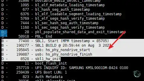
D - 11 - boot_flash_init
This is why the serial log maps so neatly to the table-driven boot sequence: each procedure is executed in order and timed, and the log reflects that sequence.
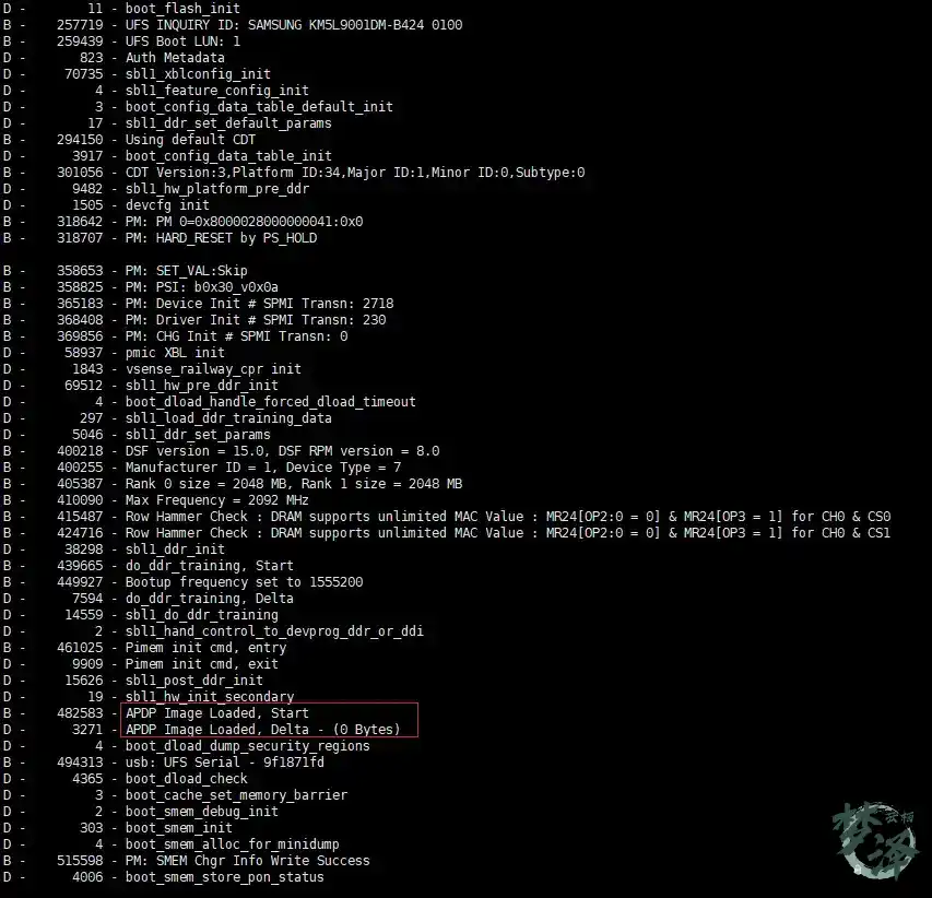
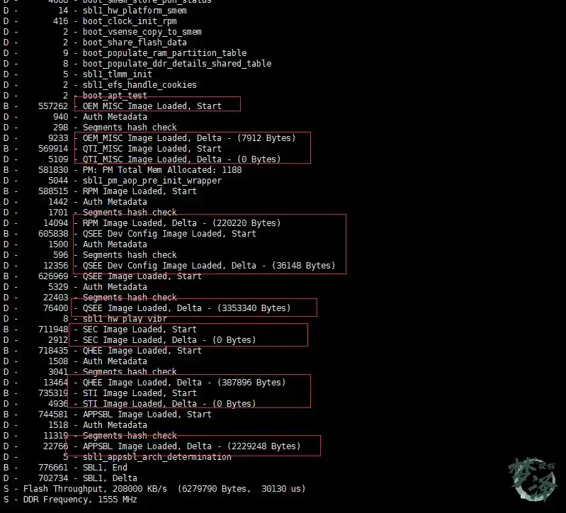
Messages such as Image load Start, APDP Image Loaded, Delta, and Image_Load,Start are the visible trace of boot_config_process_entry. The load / verify / execute pattern repeats for subsystems like RPM and QSEE. Only later, in ABL, does the system move on to loading the kernel and launching HLOS.
Looking more closely at SBL internals
The SBL path above already covers the main control flow, but a few functions are worth isolating for closer study.
sbl1_xblconfig_init
sbl1_xblconfig_init->xblconfig_init
This is the initialization entry into XBL configuration handling.
sbl1_hw_pre_ddr_init and PMIC bring-up
One of the important branches inside pre-DDR hardware setup is PMIC initialization, especially boot_pm_device_init:
static int abs(int x) { return x >= 0 ? x : -x; }

pm_err_flag_type
pm_device_init ( void )
{
   static pm_err_flag_type err_flag = PM_ERR_FLAG_SUCCESS;
   uint32 initial_num_spmi_transn = pm_get_num_spmi_transaction(0);

   err_flag |= pm_device_setup();//SPMI bus初始化

   pm_target_information_init();

   if( (pm_is_target_pre_silicon() == TRUE) && (pm_is_pmic_present(PMIC_A) == FALSE) )
   {
      pm_log_message("Bootup: No PMIC on RUMI Target");
      return err_flag = PM_ERR_FLAG_SUCCESS;
   }

   pm_comm_info_init();

   err_flag |= pm_device_pre_init();

   err_flag |= pm_pon_init(); //PON机制的初始化

   err_flag |= pm_pbs_info_rom_init();  /* Read PBS INFO for the pmic rom devices */

   err_flag |= pm_sbl_pre_config(); /* SBL Pre Configuration */

   err_flag |= pm_sbl_config(); /* SBL Configuration */
   if (err_flag == PM_ERR_FLAG_SUCCESS)
   {
      pm_ram_image_loaded_flag = TRUE;
   }

   err_flag |= pm_sbl_config_test(); /* SBL Configuration validation, only executes complete code if spare reg 0x88F bit 0 is set*/

   err_flag |= pm_pbs_info_ram_init();  /* Read PBS INFO for the pmic ram devices */

   err_flag |= pm_pbs_ram_version_validation_test(); /* PBS RAM Version validation, only executes complete code if spare reg 0x88F bit 0 is set*/

   err_flag |= pm_device_post_init(); /* Initialize PMIC with the ones PDM can not perform */

  //Write to Spare bit for pm_device_init_status
   if(err_flag == PM_ERR_FLAG_SUCCESS)
   {
      err_flag = pm_comm_write_byte_mask(PMIC_A_SLAVEID_PRIM, PMIO_PON_PERPH_RB_SPARE_ADDR, PON_PERPH_RB_SPARE_DEVICE_INIT_MASK,PON_PERPH_RB_SPARE_DEVICE_INIT_MASK, 0);
   }

   pm_log_message("Device Init # SPMI Transn: %d", pm_get_num_spmi_transaction(initial_num_spmi_transn));
   return err_flag; /* NON ZERO return means an ERROR */
}
The details of PMIC flow are extensive on their own, but even at a high level, this function shows how early power management and bus configuration are tied directly into whether the rest of boot can proceed.
Board ID and platform identification
Functions such as sbl1_hw_reset_platform_type and sbl1_hw_reset_platform_version are tied to Qualcomm platform board ID design. These values influence downstream configuration selection, including things such as device tree choice.
Why UEFI enters the picture
To understand modern Qualcomm ABL, it helps to place UEFI in context.
Traditional PCs relied on BIOS to initialize hardware, test basic functionality, and start the operating system. UEFI is the newer model: a standardized firmware interface between pre-boot firmware and the OS, intended to replace BIOS and simplify startup.
One of the key historical reasons for the shift is that 64-bit processor architectures are not a good fit for legacy BIOS’s 16-bit execution model. UEFI redefines the firmware/OS interface as a more extensible and standardized specification.
UEFI compared with BIOS
<table> <thead> <tr> <th>Item</th> <th>UEFI</th> <th>BIOS</th> <th>Description</th> </tr> </thead> <tbody> <tr> <td>Development model</td> <td>Open interfaces, standardized APIs, mostly C code</td> <td>Closed, inconsistent interfaces, mostly assembly</td> <td>BIOS stagnated in part because of its closed design and awkward interfaces. UEFI’s standardization and C-centric implementation dramatically lowered development complexity.</td> </tr> <tr> <td>Performance</td> <td>Asynchronous model + timer interrupt</td> <td>Interrupt-driven model</td> <td>UEFI drops the inefficient dependence on external hardware interrupts and uses asynchronous/event-based mechanisms for much better performance.</td> </tr> <tr> <td>Extensibility and compatibility</td> <td>Modular driver design</td> <td>Static linking</td> <td>UEFI supports modular growth through dynamic loading. BIOS is constrained by 16-bit mode and limited addressing. UEFI supports 64-bit programs and remains compatible with 32-bit designs.</td> </tr> <tr> <td>Security</td> <td>Includes signed driver validation and security mechanisms</td> <td>Security was not a design focus</td> <td>UEFI introduces signature verification and stronger security assumptions.</td> </tr> <tr> <td>Drive capacity</td> <td>Supports drives larger than 2 TB</td> <td>Does not support drives larger than 2 TB</td> <td>Legacy BIOS partitioning based on 32-bit LBA limits practical capacity; UEFI supports a much larger address space.</td> </tr> <tr> <td>File system support</td> <td>Yes</td> <td>No</td> <td>UEFI behaves much more like a small OS and can read files directly from FAT partitions.</td> </tr> <tr> <td>Applications</td> <td>Can run EFI applications directly</td> <td>No</td> <td>This makes OS installers and utilities much easier to launch than the old sector-based BIOS model.</td> </tr> </tbody> </table>UEFI and the Android bootloader idea
UEFI first became dominant in the PC world, where UEFI + GPT displaced BIOS + MBR. The same trend has influenced Android bootloader evolution.
Android booting has gone through multiple implementations, from older bootloader styles to LK, and then toward UEFI. In practice, the word bootloader can be confusing because it is used in two ways:
- as the name of an older style of bootstrap program
- as a generic umbrella term for the firmware stage that boots the OS
Under the broader meaning, UEFI, LK, and even BIOS can all be discussed as bootloader implementations. So when talking about Android startup at a system level, it is often enough to think of UEFI as the current form of that loader layer.
What UEFI is, in one sentence
UEFI is a specification: a software interface that connects the operating system to platform firmware that implements the spec.
The UEFI/XBL execution path
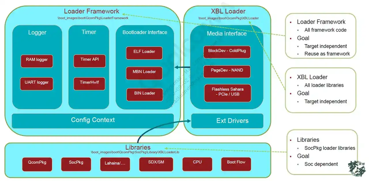
XBL Loader architecture
Runtime flow of XBL Core / UEFI
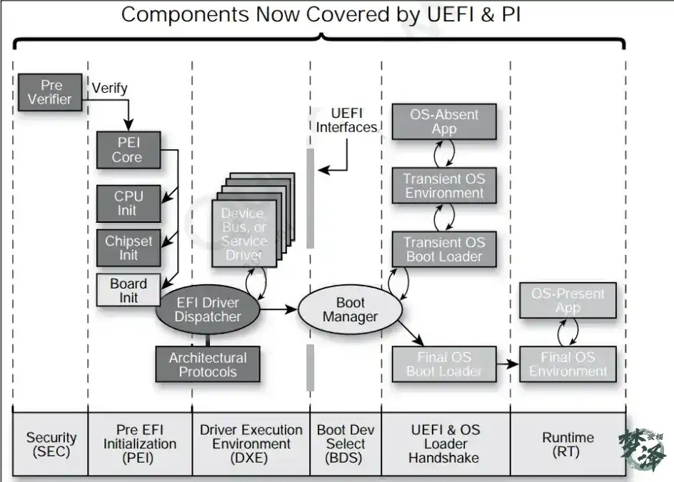
The UEFI execution sequence is:
SEC -> PEI -> DXE -> BDS -> UEFI Loader -> RT
SEC phase: assembly entry and C entry
Assembly entry: ModuleEntryPoint.masm
SEC assembly entry is located at:
BOOT.XF.4.1/boot_images/QcomPkg/XBLCore/ModuleEntryPoint.masm
Its entry symbol is _ModuleEntryPoint.
#include <AsmMacroIoLibV8.h>
#include <Base.h>
#include <Library/PcdLib.h>
#include <AutoGen.h>

    AREA    |.text|,ALIGN=8,CODE,READONLY

    IMPORT CEntryPoint// 导入CEntryPoint()函数
    EXPORT _ModuleEntryPoint// 输出 _ModuleEntryPoint段
    IMPORT ArmWriteCpacr// 导入InitStackCanary()函数 初始化栈
    IMPORT ArmEnableInstructionCache//导入ArmDisableInterrupts()函数 禁用arm 中断
    IMPORT ArmInvalidateInstructionCache// 导入ArmDisableCachesAndMmu()函数 禁用cache, mmu
    IMPORT ArmInvalidateTlb
    IMPORT ArmEnableDataCache
    IMPORT InitStackCanary

  IMPORT  ArmDisableInterrupts
  IMPORT  ArmDisableCachesAndMmu
  IMPORT  ArmWriteCptr
  IMPORT  ArmDisableAlignmentCheck
  IMPORT  ArmWriteHcr
  IMPORT  ArmWriteVBar
  IMPORT  ArmInvalidateDataCache

// TODO - JDG
    EXPORT _StackBase
    EXPORT _StackSize
    EXPORT CNTFRQ

_StackBase
  dcq FixedPcdGet64(PcdPrePiStackBase)

_StackSize
  dcq FixedPcdGet64(PcdPrePiStackSize)

CNTFRQ
  dcq FixedPcdGet32(PcdArmArchTimerFreqInHz)

_ModuleEntryPoint
  mov x0, #0
  /* First ensure all interrupts are disabled */
  bl ArmDisableInterrupts        //关闭所有的中断

  /* Ensure that the MMU and caches are off */
  bl ArmDisableCachesAndMmu        //关闭MMU和caches

  /* Invalidate Instruction Cache and TLB */
  bl ArmInvalidateInstructionCache    //关闭TLB

  bl ArmInvalidateTlb

  /* Get current EL in x0 */
  //获得当前运行的安全环境:EL1、EL2、EL3
  EL1_OR_EL2_OR_EL3(x0)
// CurrentEL : 0xC = EL3; 8 = EL2; 4 = EL1
// This only selects between EL1 and EL2 and EL3, else we die.
// Provide the Macro with a safe temp xreg to use.
        //mrs    x0, CurrentEL
        cmp    x0, #0xC// 比较 x0寄存器是否为 0xc,如果是跳转到 标签3
        beq   %F3
        cmp    x0, #0x8// 比较 x0寄存器是否为 0x8,如果是跳转到 标签2
        beq   %F2
        cmp    x0, #0x4// 比较 x0寄存器是否为 0x4
        bne   .                    // We should never get here
// EL1 code starts here

1  beq _Start
2  beq _Start// 如果当前是 EL2,直接跳转到_Start

  /* Do not trap any access to Floating Point and Advanced SIMD in EL3. */
  /* Note this works only in EL3, x0 has current EL mode */
3  mov x0, #0
  bl ArmWriteCptr// 如果当前是 EL3,直接跳转到ArmWriteCptr

//初始化ELX 安全环境
_SetupELx
  mov x0, #0x30           /* RES1 */// x0 = 0x30
  orr x0, x0, #(1 << 0)   /* Non-secure bit */// 使能第0位为1
  orr x0, x0, #(1 << 8)   /* HVC enable */// 使能第8位为1
  orr x0, x0, #(1 << 10)  /* 64-bit EL2 */// 使能第10位为1
  msr scr_el3, x0

// ...
// ...
// ...

//使能 Cache
_EnableCache
#ifdef PRE_SIL
  LoadConstantToReg (FixedPcdGet32(PcdSkipEarlyCacheMaint), x0)
  cmn x0, #0
b.ne _PrepareArguments
#endif
  bl ArmInvalidateDataCache
  bl ArmEnableInstructionCache
  bl ArmEnableDataCache

//初始化栈
_PrepareArguments
  /* Initialize Stack Canary */
  bl InitStackCanary

//调用 CEntryPoint,传参 _StackBase、_StackSize
  /* x0 = _StackBase and x1 = _StackSize */
  ldr x0, _StackBase     /* Stack base arg0 */
  ldr x1, _StackSize     /* Stack size arg1 */
  bl CEntryPoint //进入C

dead
  b dead                      /* We should never get here */

END
The assembly stage does a small but essential set of tasks:
- Disable all interrupts.
- Disable MMU and caches.
- Invalidate instruction cache and TLB.
- Determine the current exception level.
- Set up the required EL/security environment.
- Re-enable caches in the intended way.
- Initialize stack protection.
- Call
CEntryPointwith stack base and size.
SEC C entry: XBLCore/Sec.c
The assembly stage is mainly there to prepare a C runtime environment. The SEC C entry is in:
BOOT.XF.4.1/boot_images/QcomPkg/XBLCore/Sec.c
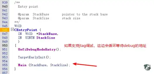
The central function is Main:
VOIDMain (INVOID  *StackBase,INUINTNStackSize){
EFI_STATUSStatus =EFI_NOT_READY;
UefiInfoBlkType*UefiInfoBlkPtr =NULL;
UINT64UefiFdBase = 0,SecHeapMemBase = 0;
UINTNSecHeapAslrVal = 0;
UINTNHobStackSize;
UINTNUARTLogBufferSize = 0;
UINTN            *UARTLogBufferPtr;
MemRegionInfoDxeHeapMemInfo;
UINTNDxeHeapAslrVal = 0;

gReset =GetTimeInNanoSecond(GetPerformanceCounter());
  //获得fdf文件所在的地址,fdf可以说是UEFI的配置文件
  //在fdf文件中包含所有的inf文件所在路径,及相关的bmp图片资源路径,以及相关的cfg配置文件路径UefiFdBase =FixedPcdGet64(PcdEmbeddedFdBaseAddress);
SecHeapMemBase =UefiFdBase +SEC_HEAP_MEM_OFFSET;
HobStackSize =StackSize;

gStackBase =StackBase;

  /* Start UART debug output */
UartInit();    //初始化串口

PrintUefiStartInfo(); //打印一些串口log
  //这边加了log 来确定M7项目的UefiFdBase,StackBase,StackSize
  //LIUQI: gStackBase = 0x000000005FF90000
  //LIUQI: StackSize = 0x000000000003FD00
  //LIUQI: UefiFdBase = 0x000000005FC00000
  SerialPrint("LIUQI: gStackBase = 0x%016lx\\n", gStackBase);
  SerialPrint("LIUQI: StackSize = 0x%016lx\\n", StackSize);
  SerialPrint("LIUQI: UefiFdBase = 0x%016l\\nx", UefiFdBase);

  /* Get nibble from random value to adjust SEC heap */
SecHeapAslrVal =AslrAdjustRNGVal(ASLR_HEAP_RNG_BITS);

InitHobList(SecHeapMemBase,
SEC_HEAP_MEM_SIZE - (SecHeapAslrVal*ASLR_HEAP_ALIGN),
UefiInfoBlkPtr);

  // Need memory allocation working
InitializeCpuExceptionHandlers (NULL); //初始化CPU异常处理入口PrintTimerDelta(); //打印从开机到现在的时间差

  /* Enable program flow prediction, if supported *///  ArmEnableBranchPrediction ();/* Initialize Info Block */
UefiInfoBlkPtr =InitInfoBlock (UefiFdBase +UEFI_INFO_BLK_OFFSET);
UefiInfoBlkPtr->StackBase =StackBase;
UefiInfoBlkPtr->StackSize =StackSize;

  //初始化 RAM 分区表InitRamPartitionTableLib ();

ValidateFdRegion(UefiFdBase);

  /* Add the FVs to the hob list */
  //初始化hoblist,有关hob可参考:<https://opqqrjk1dc.feishu.cn/wiki/wikcnabfL0g6PS10ctRWRfzX9bcBuildFvHob> (PcdGet64(PcdFlashFvMainBase),PcdGet64(PcdFlashFvMainSize));

  /* Should be done after we have setup HOB for memory allocation  */
  //打印RAM 分区信息PrintRamPartitions ();

  //初始化cacheStatus =EarlyCacheInit (UefiFdBase,UEFI_FD_SIZE);

  /* Load and Parse platform cfg file, cache re-initialized per cfg file */
  //加载并解析 uefiplat.cfg平台配置文件Status =LoadAndParsePlatformCfg();

  //更新系统内存区相关信息
  /* Add information from all other memory banks */
Status =UpdateSystemMemoryRegions();
  /* Initialize cache for all memory regions */
Status =InitCacheWithMemoryRegions();

  //初始化所有的共享库
  /* All shared lib related initialization */
Status =InitSharedLibs();

  //获得DXE Heap堆内存信息,uefiplat.cfg中定义的Status =GetMemRegionInfoByName("DXE Heap", &DxeHeapMemInfo);

  /* Get nibble from random value to adjust DXE heap */
DxeHeapAslrVal =AslrAdjustRNGVal(ASLR_HEAP_RNG_BITS);

  /* Re-initialize HOB to point to the DXE Heap in CFG */
ReInitHobList(DxeHeapMemInfo.MemBase,
DxeHeapMemInfo.MemSize - (DxeHeapAslrVal*ASLR_HEAP_ALIGN),
UefiInfoBlkPtr);

    /* Update UART log buffer size if specififed in uefiplat else allocate 32KB of serial buffer in DXE Heap. */
  //在uefiplat.cfg中定义,可以调整uart的buffer size,目前M7此项注释掉了
Status =GetConfigValue ("UARTLogBufferSize", (UINT32*) &UARTLogBufferSize);

  // Allocate Runtime Pool
  //初始化分页池缓存区UARTLogBufferPtr =AllocatePagesRuntimeServiceData(EFI_SIZE_TO_PAGES(UARTLogBufferSize));

  /* Prevent Reinitializing of Serial Buffer */
SerialBufferReInitLock();

  /* Now we have access to bigger pool, move pre-pi memory allocation pool to it */
ReInitPagePoolBuffer ();

InitSplitBoot (&UefiBootContinue, 0);  // Doesn't return if succeeds

UefiBootContinue (0);  // Just continue booting explicitly if returns or on failure
}
At a high level, this function:
- initializes UART for debug output
- establishes SEC heap and HOB structures
- installs CPU exception handlers
- validates firmware volume layout
- initializes RAM partition data and cache handling
- parses
uefiplat.cfg - updates memory region information
- initializes shared libraries
- switches to the DXE heap and continues boot with
UefiBootContinue
LoadAndParsePlatformCfg
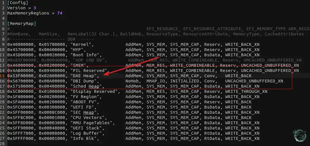
This function is important because it turns the platform configuration file into concrete memory and policy data used by the rest of the firmware.
Its main tasks are:
- Initialize global state.
- Load and parse
uefiplat.cfg. - Parse the
[Config]section. - Parse the
[MemoryMap]section. - Parse the
[RegisterMap]section into memory-region data. - Parse
[ConfigParameters]intoConfigTableandConfigTableEntryCount. - Parse
[ChipIDConfig].
EFI_STATUSEFIAPILoadAndParsePlatformCfg (VOID ){
EFI_STATUSStatus;
INTNMemParserDesc = 0;
UINT8 *CfgBuffer =NULL;
UINTNFileSize = 0;
//1.初始化相关全局变量InitGlobals();
//2. 加载并解析 uefiplat.cfg 配置文件Status =LoadFileFromFV0 (UEFIPLATCFG_FILE, &CfgBuffer, &FileSize);
MemParserDesc =OpenParser (CfgBuffer,FileSize,NULL);
/* Reset Global for RAM load */
mMemRegions =NULL;
mNumMemRegions = 0;
//3. 解析uefiplat.cfg 中的 [Config] 区域EnumKeyValues (MemParserDesc, (UINT8*)"Config",ProcessConfigTokens)
MemParserDesc =ReopenParser (MemParserDesc);
//4. 解析uefiplat.cfg 中的 [MemoryMap] 区域EnumCommaDelimSectionItems (MemParserDesc, (UINT8*)"MemoryMap",ProcessMemoryMapTokens)
GetCfgMemMapBounds();
//UpdateSystemMemoryRegions();
MemParserDesc =ReopenParser (MemParserDesc);
//5. 解æžuefiplat.cfg ä¸çš��?[RegisterMap] 区域,å†EnumCommaDelimSectionItems (MemParserDesc, (UINT8*)"RegisterMap",ProcessMemoryMapTokens)
MemParserDesc =ReopenParser (MemParserDesc);
/* Reset for RAM load */
ConfigTable =NULL;
ConfigTableEntryCount = 0;
// 6. 解析uefiplat.cfg 中的 [ConfigParameters] 区域// 内容保存在 ConfigTable 中,ConfigTableEntryCount表示其内容的数量EnumKeyValues (MemParserDesc, (UINT8*)"ConfigParameters",ParseConfigParameters)
MemParserDesc =ReopenParser (MemParserDesc);
//7. 解析uefiplat.cfg 中的 [ChipIDConfig] 区域EnumCommaDelimSectionItems (MemParserDesc, (UINT8*)"ChipIDConfig",ParseChipIDConfigParameters) < 0
CloseParser(MemParserDesc);
returnEFI_SUCCESS;
ErrorExit:
DEBUG ((EFI_D_ERROR, "Failed LoadAndParsePlatformCfg\\r\\n"));
CpuDeadLoop();
returnStatus;
}
UefiBootContinue
After SEC setup is complete, UefiBootContinue builds the HOBs needed for the next phase and then hands off to DXE.
void UefiBootContinue(void* arg){
  //EFI_STATUS       Status = EFI_NOT_READY;
  UINT32          UefiStartTime= 0;
  UefiInfoBlkType* UefiInfoBlkPtr= NULL;
  UINTN           HobStackSize= 0;

  //...

  //创建Stack、CPU Hob信息
  BuildStackHob((EFI_PHYSICAL_ADDRESS)gStackBase, HobStackSize);
  BuildCpuHob(PcdGet8(PcdPrePiCpuMemorySize), PcdGet8(PcdPrePiCpuIoSize));

  /* Build HOB to pass up prodmode info for security applications */
  gProdmodeInfo= JTAGDebugDisableFusesBlown();
  BuildGuidDataHob(&gQcomProdmodeInfoGuid, &gProdmodeInfo, sizeof(BOOLEAN));

  //Display 早期初始化
  DisplayEarlyInfo();

  AddMemRegionHobs();

  /* Start perf here, after timer init, start at current tick value */
  //开启耗费的时间统计,用于计算性能
  InitPerf();

  /*Add performance hob for pei performance data*/
  AddPerformanceHob(gReset);

  //...

  /* Any non-critical initialization */
  TargetLateInit();

  /* Build memory allocation HOB for FV2 type
     Need to remove for decompressed image */
  BuildMemHobForFv(EFI_HOB_TYPE_FV2);

  SetUefiCrashCookie();

  SetUefiTargetReset();

  /* Load the DXE Core and transfer control to it */
  //åŠ è½½ä¸”å°†CPU交
  LoadDxeCoreFromFv(NULL, 0);

  /* DXE Core should always load and never return */
  ASSERT(FALSE);
  CpuDeadLoop();
}
One noteworthy step here is DisplayEarlyInfo(), which performs early display-related initialization and also reports firmware information.
Its flow includes:
- Reading UEFI core configuration fields, such as
PlatConfigFileName="uefiplatLA.cfg". - Reading the firmware version string, for example from a DSC definition like
gEfiMdeModulePkgTokenSpaceGuid.PcdFirmwareVersionString|L"4.2". - Selecting the matching image based on firmware version.
- Printing firmware version information.
- Determining the boot path preference, typically in the order UFS > eMMC > SPI.
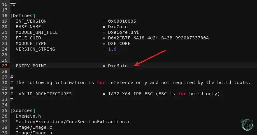
DXE: the driver execution environment
After the previous handoff, execution enters DXE through LoadDxeCoreFromFv().
This function locates the DXE_CORE file, loads it with LoadDxeCoreFromFfsFile, and transfers control to its entry point, DxeMain().
The code is under:
BOOT.XF.1.4/boot_images/MdeModulePkg/Core/Dxe/DxeMain.inf
The DXE internals are complex, but the broad responsibilities are easier to summarize:
- Initialize CPU exception handling.
- Initialize memory and the basic execution environment for UEFI code.
- Initialize the DXE dispatcher.
At the end of this process, control moves into BDS:
//函数最后会跳转bds
gBds->Entry (gBds);
BDS: selecting the boot path
BDS code is located in:
BOOT.XF.4.1/boot_images/QcomPkg/Drivers/BdsDxe/BdsDxe.inf
Its core responsibilities are:
- Register hotkey events. When a key is pressed, the flow reaches
HotkeyEvent()and ultimatelyHotkeyCallback(), where the key scancode is interpreted. - Perform platform BDS initialization.
- Initialize all drivers on the
DriverOptionList. - Start the selected boot target.
The entry function looks like this:
// BOOT.XF.4.1/boot_images/QcomPkg/Drivers/BdsDxe/BdsEntry.c
VOID EFIAPI BdsEntry(IN EFI_BDS_ARCH_PROTOCOL  *This)
{
  // 1. 注册按键事件,按下按键后会回调到HotkeyEvent() 函数,最终调用到HotkeyCallback()函数中,解析其中的key scancode
  // Initialize hotkey service
  InitializeHotkeyService ();
  // 2. 平台BDS初始化,在其中会打印显示版本号,平台版本信息等等,调用LaunchDefaultBDSApps ()加载默认APP,调用SetupPlatformSecurity()初始化secureboot安全环境,挂载efisp分区,调用ReadAnyKey() 循环检测音量下键是否按下,从而更新对应的启动项
  PlatformBdsInit ();

  // 3. 初始化所有 DriverOptionList 上的 驱动协议。
  // Set up the device list based on EFI 1.1 variables
  // process Driver#### and Load the driver's in the driver option list
  BdsLibLoadDrivers (&DriverOptionList);

  // Check if we have the boot next option
  mBootNext = BdsLibGetVariableAndSize ( L"BootNext",&gEfiGlobalVariableGuid,&BootNextSize );

  // Setup some platform policy here
  PlatformBdsPolicyBehavior (&DriverOptionList, &BootOptionList, BdsProcessCapsules, BdsMemoryTest);
  // 4. 根据选择的启动方式,启动对应的的系统,  启动sheLl app
  // BDS select the boot device to load OS
  BdsBootDeviceSelect ();

  // Only assert here since this is the right behavior, we should never
  // return back to DxeCore.
  ASSERT (FALSE);
  return ;
}
During PlatformBdsInit(), the firmware typically:
- prints firmware and platform version information
- calls
LaunchDefaultBDSApps()to load default applications - calls
SetupPlatformSecurity()to initialize Secure Boot state - mounts the EFI system partition
- polls for key input, such as volume-down, to update boot selection
RT phase
Runtime code is under:
BOOT.XF.4.1/boot_images/MdeModulePkg/Core/RuntimeDxe/Runtime
This phase is much less central when the goal is to understand early Android boot bring-up, so it is usually not where initial debugging effort is focused.
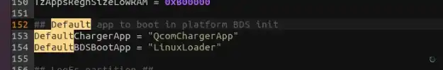
Default UEFI apps and the charger path
As part of BDS initialization, LaunchDefaultBDSApps() loads the default applications defined in uefiplat.cfg.
The typical sequence is:
- Parse
DefaultChargerAppfromuefiplat.cfgintoDefaultApp. - Load the QcomChargerApp application using
gMainFvGuidand the configured name. - Parse
DefaultBDSBootAppfromuefiplat.cfg. - Load
DefaultBDSBootApp, which does not return on success.
EFIAPILaunchDefaultBDSApps (VOID){

EFI_STATUSStatus =EFI_SUCCESS;
CHAR8DefaultApp[DEF_APP_STR_LEN];
UINTNSize =DEF_APP_STR_LEN;
CHAR8FileinFV[64] = {0};
  //1.解析 uefiplat.cfg中的DefaultChargerApp,字符串保存在DefaultApp数组中Status =GetConfigString ("DefaultChargerApp",DefaultApp, &Size);
AsciiStrCpy (FileinFV,FILE_IN_FV_PREPEND);
AsciiStrCat (FileinFV,DefaultApp);

  if (Status ==EFI_SUCCESS)
  {
    //2. 加载QcomChargerApp 应用程序,传参gMainFvGuid 和 “DefaultChargerApp”Status =LoadImageFromFV (FileinFV,NULL );
    if (EFI_ERROR(Status))
DEBUG((EFI_D_ERROR, "Failed to launch default charger app, status: %r\\n",Status));
  }

Size =DEF_APP_STR_LEN;
  // 3. 解析 uefiplat.cfg中的DefaultBDSBootApp,字符串保存在DefaultApp数组中。Status =GetConfigString ("DefaultBDSBootApp",DefaultApp, &Size);
  if (Status ==EFI_SUCCESS)
  {
DisplayPOSTTime ();
    //4. 加载DefaultBDSBootApp 应用程序,加载后不再返回LaunchAppFromGuidedFv(&gEfiAblFvNameGuid,DefaultApp,NULL);
    //If we return from above function, considered a failure
ConfirmShutdownOnFailure();
  }
  else
  {
DEBUG ((EFI_D_INFO, "[QcomBds] No default boot app specified\\n"));
  }

  returnStatus;
}
This is the bridge between platform policy and the actual application that continues Android boot.
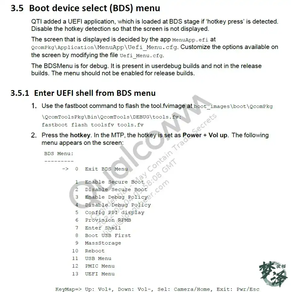
UEFI and ABL
Options can be customized in:
BOOT.XF.4.1/boot_images/QcomPkg/QcomToolsPkg/MenuApp/Uefi_Menu.cfg
Within LaunchDefaultBDSApps, the firmware loads the DefaultChargerApp and DefaultBDSBootApp defined in uefiplat.cfg.
In this setup, LinuxLoader is a UEFI Application, and that code belongs to the AP-side ABL.
That also marks the practical transition point in this startup path: the earlier Qualcomm boot stages prepare clocks, DDR, PMIC state, security context, shared memory, firmware volumes, and platform policy; then UEFI BDS launches the application that continues into the Android boot flow proper.
Once the chain reaches ABL, the focus shifts from building subsystem execution environments to loading the kernel and starting HLOS.